
Electrical Design
The electrical design of our TRACTOR consisted of the following main sub-systems:
Power Distribution
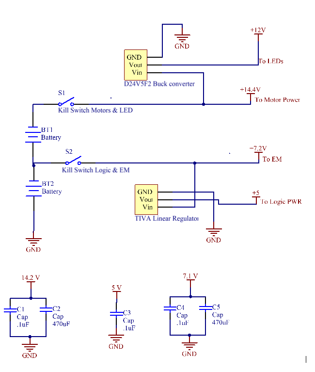
Our power distribution circuit aimed to reduce conductive coupling noise by eliminating common impedance as much as possible. This was done by using power rails that would allow all sub-systems to connect to power and ground as close to the source as possible. The circuit diagram is shown below. A buck converter from Pololu (D24V5F2) was used to convert the 14.4 V from the batteries into 12 V to power the LED strip. Sensors where powered off the TIVA, using the linear regulator built into the protection board.
- Power Distribution
- MINER Detection circuit
- Accelerometer
- Motor Drive Circuit
- Electromagnet Circuit
- LED Circuit
- Color Sensor Circuit
- IR sensing Circuit
- Limit Switch Circuit
- Team Switch Button
- SPUD Communication Circuit
Power Distribution
Our power distribution circuit aimed to reduce conductive coupling noise by eliminating common impedance as much as possible. This was done by using power rails that would allow all sub-systems to connect to power and ground as close to the source as possible. The circuit diagram is shown below. A buck converter from Pololu (D24V5F2) was used to convert the 14.4 V from the batteries into 12 V to power the LED strip. Sensors where powered off the TIVA, using the linear regulator built into the protection board.
MINER Detection circuit
We used a tape sensor to detect whether or not our robot had grabbed a MINER. The photo-transistor in the tape sensor was incorporated in a trans-resistive circuit, whose output was turned into a binary value by a hex inverter (SN74HC14).
We used a tape sensor to detect whether or not our robot had grabbed a MINER. The photo-transistor in the tape sensor was incorporated in a trans-resistive circuit, whose output was turned into a binary value by a hex inverter (SN74HC14).

Accelerometer
Communication with the accelerometer was via SPI protocol. The SSI2 module on the TIVA was used.
Communication with the accelerometer was via SPI protocol. The SSI2 module on the TIVA was used.

Motor Drive Circuit
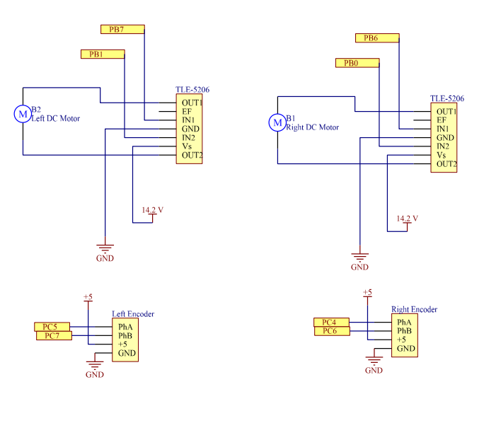
TLE-5206 H-bridges were used to drive our motors. This driver was chosen given for its high current-carrying capability (5A). The motors provided had an internal resistance of ~10 Ohm, which translated to a stall current close to 1.4 A, when operating at 14.2 V. Low R_DS,ON values of 200 mOhm also made this H-bridge attractive. The H-bridges were driven by a PWM pin and a digital pin each.
To close the loop on our motor control, we used Pololu 4761 magnetic encoders. Phase A on each encoder was connected to an interrupt pin on the TIVA, while the other was connected to a digital pin, and used to determine rotation direction.
Electromagnet Circuit
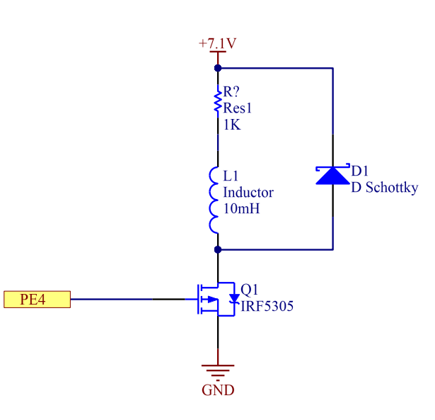
We used an electromagnet to grab and move MINERs. The electromagnet was driven by a power MOSFET, and was connected to a fly-by diode to protect our circuitry and reduce inductive coupling.
We used an electromagnet to grab and move MINERs. The electromagnet was driven by a power MOSFET, and was connected to a fly-by diode to protect our circuitry and reduce inductive coupling.

LED Circuit
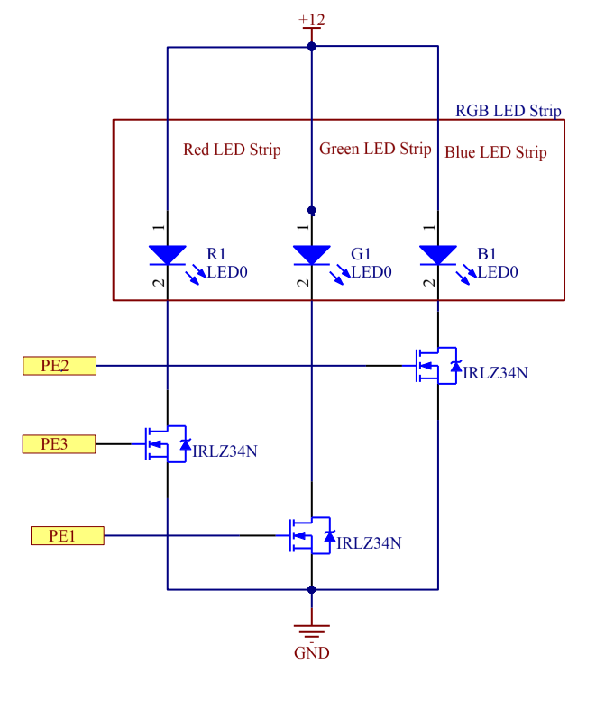
We used an RGB LED strip to communicate the team that our robot was playing in, as well as the permit status (LEDs flashing indicated permits were issued).
We used an RGB LED strip to communicate the team that our robot was playing in, as well as the permit status (LEDs flashing indicated permits were issued).
Color Sensor Circuit
Our robot used a color sensor to close the loop on its navigation algorithm. This color sensor communicated with the TIVA via I2C protocol, using a library provided by the teaching staff.
Our robot used a color sensor to close the loop on its navigation algorithm. This color sensor communicated with the TIVA via I2C protocol, using a library provided by the teaching staff.

IR sensing Circuit
Our robot used an IR sensing to find a MINER once it was sufficiently close to it. This was done using an IR photo-transistor, connected to a trans-resistive circuit. The output signal was the AC-coupled to ensure that different environmental conditions (day vs. night) would not affect performance. The signal was then amplified and made into a digital output by means of a Schmitt trigger.
Our robot used an IR sensing to find a MINER once it was sufficiently close to it. This was done using an IR photo-transistor, connected to a trans-resistive circuit. The output signal was the AC-coupled to ensure that different environmental conditions (day vs. night) would not affect performance. The signal was then amplified and made into a digital output by means of a Schmitt trigger.
Limit Switch Circuit
Collisions were detected using limit switches, located at the front-most and rear-most points of the vehicle. Two limit switches connected in parallel constituted each of the collision detection circuits. The internal pull-up resistor on the TIVA was enabled, allowing for a cleaner circuit design.
Collisions were detected using limit switches, located at the front-most and rear-most points of the vehicle. Two limit switches connected in parallel constituted each of the collision detection circuits. The internal pull-up resistor on the TIVA was enabled, allowing for a cleaner circuit design.

Team Switch Button
To switch teams, we used one of the built-in buttons on the TIVA, which is internally connected to pin PF4.
SPUD Communication Circuit
To obtain game-related information we relied on the SPUD (provided), which communicated with the TIVA via SPI. Module SSI0 on the TIVA was used.

